


- Placa base de nuestra PS3.
- Infectus ModChip. (Para encontrarlo no tenéis más que buscar por Google)
- Cable IDE 30 awg. (Son los cables anchos de los discos duros)
- Estación de soldadura y estaño.
- Epoxy o cualquier otra forma de sujección.


| ¿El qué? | ¿De dónde? | ¿Cuanto? |
| Motor / generador. | Ebay. | $26,00 = 18,27€ |
| Varios de tubería. | Ferretería. | $41,49 = 29,16€ |
| Tubería para las palas. | Ferretería. | $12,84 = 9,02€ |
| Varios equipos. | Ferretería. | $8,00 = 5,6€ |
| Conductos. | Ferretería. | $19,95 = 14,02€ |
| Madera y aluminio. | Montón de chatarra | $0,00 |
| Cable de alimentación | Ya lo tenía. | $0,00 |
| Cuerda y tensores. | Ferretería. | $18,47 = 12,98€ |
| Piezas electrónicas | Ya lo tenía. | $0,00 |
| Relé | Almacén de coches. | $13,87 = 9,74€ |
| Batería. | Cogida de mi UPS. | $0,00 |
| Inversor | Ya lo tenía. | $0,00 |
| Pintura | Ya lo tenía. | $0,00 |
| Total | $140,62 = 98,84€ |
- Montar los componentes electrónicos en una caja estanca.- Añadir medidores para la tensión de la batería y la de la turbina.- Añadir un tacómetro para saber lo rápido que está girando.- Añadir más baterías.- Añadir otra turbina de viento u otro panel solar para producir más energía.- Obtener un inversor de mayor voltaje.- Sistema de frenado de emergencia para cuando hayan vientos fuertes.- Base de hormigón para la torre.- Una torre más alta con cables y estacas de acero.
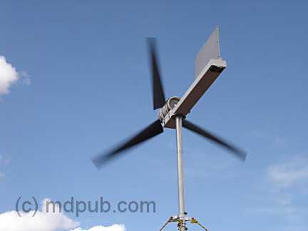 Several years ago I bought some remote property in Arizona. I am an astronomer and wanted a place to practice my hobby far away from the sky-wrecking light pollution found near cities of any real size. I found a great piece of property. The problem is, it's so remote that there is no electric service available. That's not really a problem. No electricity equals no light pollution. However, it would be nice to have at least a little electricity, since so much of life in the 21st century is dependent on it. Several years ago I bought some remote property in Arizona. I am an astronomer and wanted a place to practice my hobby far away from the sky-wrecking light pollution found near cities of any real size. I found a great piece of property. The problem is, it's so remote that there is no electric service available. That's not really a problem. No electricity equals no light pollution. However, it would be nice to have at least a little electricity, since so much of life in the 21st century is dependent on it. One thing I noticed right away about my property is that most of the time, the wind is blowing. Almost from the moment I bought it, I had the idea of being energy independent by putting up a wind turbine and making some electricity, and later adding some solar panels and a wood gasifier. This is the story of how I did it. Not with an expensive, store-bought turbine, but with a home-built one that cost hardly anything. If you have some fabricating skills and some electronic know-how, you can build one too. Let me state up front that I probably won't be able to help you out much if you decide to build your own wind turbine. This web site has become insanely popular, often taxing the bandwidth limits of the server. I get dozens of requests for help each day. I simply don't have time to answer the majority of them. Most of the questions and requests I get are the same ones over and over again. I have crated a FAQ to handle these repetitive questions. Please read it before emailing me. Simple questions, not covered by the FAQ, which only require a quick and simple answer may get replies if time permits. However, there is no way I can help you out with complex issues, teach you electronics theory, help you locate parts, build a charge controller for you, or custom design a system for you. There just aren't enough hours in the day. Sorry. Since no one seems to be reading the FAQ, I will answer the No. 1 question I get many, many times a day right here up front. Why didn't I just use an automotive alternator on my wind turbine? Automotive alternators need to spin at very high speed to produce useful amounts of power. Most wind turbines don't spin fast enough for them to work. Update: Here is a video of the wind turbine in operation. Update: Here is a video of me assembling and setting up the wind turbine on my remote off-grid property. I started the process of designing my wind turbine by Googling for information on home-built wind turbines. There are a lot of them out there in an amazing variety of designs and complexities. All of them had five things in common though:
A lot of people seemed to like to use old computer tape drive motors (surplus relics from the days when computers had big reel to reel tape drives). The best apparently are a couple of models of motor made by Ametek. The best motor made by Ametek is a 99 volt DC motor that works great as a generator. Unfortunately, they are almost impossible to locate these days. There are a lot of other Ametek motors around though. A couple of their other models make decent generators and can still be found on places like Ebay http://www.tlgwindpower.com/ametek.htm There are probably lots of other brands and models of permanent magnet DC motors available that will work well as generators. Permanent magnet DC motors work as generators, but they weren't designed to be generators. So they aren't great generators. Some types of motor are a lot worse than others. When used as generators, motors generally have to be driven far faster than their rated speed to produce anything near their rated voltage. So what you are looking for is a motor that is rated for high DC voltage, low rpms and high current. Steer away from low voltage and/or high rpm motors. You want a motor that will put out over 12 Volts at a fairly low rpm, and a useful level of current. So a motor rated for say 325 rpm at 30 Volts when used as a generator, could be expected to produce 12+ volts at some reasonably low rpm. On the other hand, a motor rated at 7200 rpm at 24 volts probably won't produce 12+ volts as a generator until it is spinning many thousands of rpm, which is way too fast for a wind turbine. So shop for motors accordingly. They don't go that cheap these days. People are catching on to the fact that they make great wind generators. Other brands will work, so don't fret about the price Ameteks are going for. Shop wisely. Anyway, The motor I got was in good shape and worked great. Even just giving the shaft a quick turn with my fingers would light a 12 volt bulb quite brightly. I gave it a real test by chucking it up in my drill press and connecting it to a dummy load. It works great as a generator, putting out easily a couple hundred Watts with this setup. I knew then that if I could make a decent set of blades to drive it, it would produce plenty of power. So Blades and a hub to connect them to were the next order of business. More online research ensued. A lot of people made their own blades by carving them out of wood. That looked like an outrageous amount of work to me. I found that other people were making blades by cutting sections out of PVC pipe and shaping them into airfoils. That looked a lot more promising to me. This web site tells you how to make a set of blades for a small wind turbine using PVC pipe. http://www.yourgreendream.com/diy_pvc_blades.php 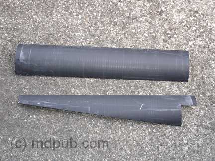 I followed their general recipe. I did things a little differently though. I used black ABS pipe since my local homecenter store just happened to have pre-cut lengths of it. I used 6 inch pipe instead of 4 inch and 24 inches long instead of 19 5/8. I started by quartering a 24 inch long piece of pipe around its circumference and cutting it lengthwise into four pieces. Then I cut out one blade, and used it as a template for cutting out the others. That left me with 4 blades (3 plus one spare). I followed their general recipe. I did things a little differently though. I used black ABS pipe since my local homecenter store just happened to have pre-cut lengths of it. I used 6 inch pipe instead of 4 inch and 24 inches long instead of 19 5/8. I started by quartering a 24 inch long piece of pipe around its circumference and cutting it lengthwise into four pieces. Then I cut out one blade, and used it as a template for cutting out the others. That left me with 4 blades (3 plus one spare). 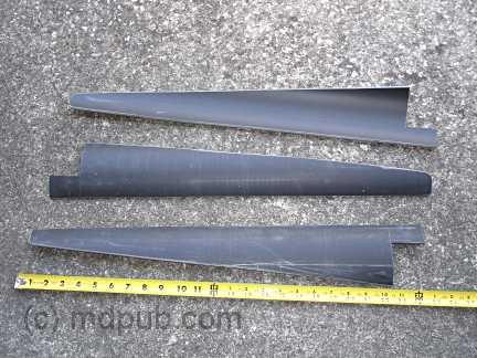 I then did a little extra smoothing and shaping using my belt sander and palm sander on the cut edges to try to make them into better airfoils. I don't know if it's really much of an improvement, but it didn't seem to hurt, and the blades look really good (if I do say so myself). I then did a little extra smoothing and shaping using my belt sander and palm sander on the cut edges to try to make them into better airfoils. I don't know if it's really much of an improvement, but it didn't seem to hurt, and the blades look really good (if I do say so myself).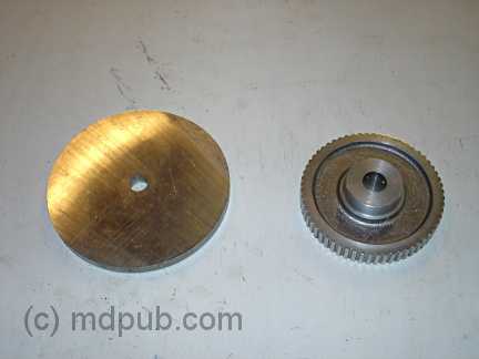 Now I needed a hub to bolt the blades to and attach to the motor. Rummaging around in my workshop, I found a toothed pulley that fit on the motor shaft, but was a little too small in diameter to bolt the blades onto. I also found a scrap disk of Aluminum 5 inches in diameter and ¼ inch thick that I could bolt the blades onto, but wouldn't attach to the motor shaft. The simple solution of course was to bolt these two pieces together to make the hub. Now I needed a hub to bolt the blades to and attach to the motor. Rummaging around in my workshop, I found a toothed pulley that fit on the motor shaft, but was a little too small in diameter to bolt the blades onto. I also found a scrap disk of Aluminum 5 inches in diameter and ¼ inch thick that I could bolt the blades onto, but wouldn't attach to the motor shaft. The simple solution of course was to bolt these two pieces together to make the hub. 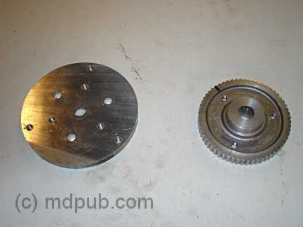 Much drilling, tapping and bolting later, I had a hub. Much drilling, tapping and bolting later, I had a hub.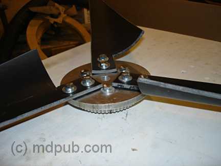 Here it is assembled and with the blades attached (after drilling mounting holes in them of course). Here it is assembled and with the blades attached (after drilling mounting holes in them of course).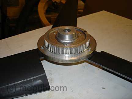 Here is another view of the hub with blades attached. Here is another view of the hub with blades attached.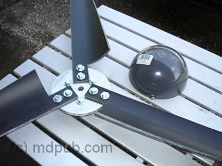 On a trip to the homecenter store for some PVC doo-dad or other for another project, I found these dome shaped vent caps. On a trip to the homecenter store for some PVC doo-dad or other for another project, I found these dome shaped vent caps. 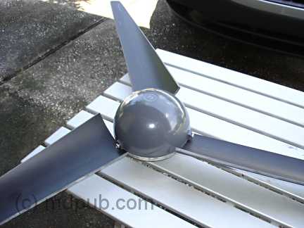 I immediately thought of adding a spinner to the hub. Wow, with that on there, it really looks like a professionally made unit. I'd never be able to convince anyone I built it myself out of junk from my workshop and plumbing parts. They'd all look at me when I said I built it myself and go "Yeah, right." Then I found a web site that claimed such spinners disrupt the airflow and hurt the efficiency of the blades. I'm not sure I believe the reasoning behind the claim, but I left the spinner off, at least initially. I immediately thought of adding a spinner to the hub. Wow, with that on there, it really looks like a professionally made unit. I'd never be able to convince anyone I built it myself out of junk from my workshop and plumbing parts. They'd all look at me when I said I built it myself and go "Yeah, right." Then I found a web site that claimed such spinners disrupt the airflow and hurt the efficiency of the blades. I'm not sure I believe the reasoning behind the claim, but I left the spinner off, at least initially.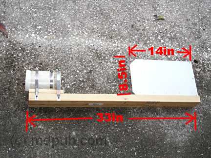 Next I needed a mounting for the turbine. Keeping it simple, I opted to just strap the motor to a piece of 2 X 4 wood. The correct length of the wood was computed by the highly scientific method of picking the best looking piece of scrap 2 X 4 off my scrap wood pile and going with however long it was. I also cut a piece of 4 inch diameter PVC pipe to make a shield to go over the motor and protect it from the weather. For a tail to keep it turned into the wind, I again just used a piece of heavy sheet Aluminum I happened to have laying around. I was worried that it wouldn't be a big enough tail, but it seems to work just fine. The turbine snaps right around into the wind every time it changes direction. For those of you always clamoring for me to provide plans, blueprints, schematics, etc., for my projects, I have added a few dimensions to the picture. I doubt any of these measurements is critical though. Next I needed a mounting for the turbine. Keeping it simple, I opted to just strap the motor to a piece of 2 X 4 wood. The correct length of the wood was computed by the highly scientific method of picking the best looking piece of scrap 2 X 4 off my scrap wood pile and going with however long it was. I also cut a piece of 4 inch diameter PVC pipe to make a shield to go over the motor and protect it from the weather. For a tail to keep it turned into the wind, I again just used a piece of heavy sheet Aluminum I happened to have laying around. I was worried that it wouldn't be a big enough tail, but it seems to work just fine. The turbine snaps right around into the wind every time it changes direction. For those of you always clamoring for me to provide plans, blueprints, schematics, etc., for my projects, I have added a few dimensions to the picture. I doubt any of these measurements is critical though.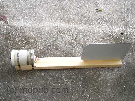 Here is another view of the completed head of the unit with the motor and tail attached. Here is another view of the completed head of the unit with the motor and tail attached.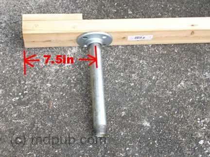 Next I had to begin thinking about some sort of tower and some sort of bearing that would allow the head to freely turn into the wind. I spent a lot of time in my local homecenter stores (Lowes and Home Depot) brainstorming. Finally, I came up with a solution that seems to work well. While brainstorming, I noticed that 1 inch diameter iron pipe is a good slip-fit inside 1 1/4 inch diameter steel EMT electrical conduit. I could use a long piece of 1 1/4 inch conduit as my tower and 1 inch pipe fittings at either end. For the head unit I attached a 1 inch iron floor flange centered 7 1/2 inches back from the generator end of the 2X4, and screwed a 10 inch long iron pipe nipple into it. The nipple would slip into the top of the piece of conduit I'd use as a tower and form a nice bearing. Wires from the generator would pass through a hole drilled in the 2X4 down the center of the pipe/conduit unit and exit at the base of the tower. Brilliant! (if I do say so myself) Next I had to begin thinking about some sort of tower and some sort of bearing that would allow the head to freely turn into the wind. I spent a lot of time in my local homecenter stores (Lowes and Home Depot) brainstorming. Finally, I came up with a solution that seems to work well. While brainstorming, I noticed that 1 inch diameter iron pipe is a good slip-fit inside 1 1/4 inch diameter steel EMT electrical conduit. I could use a long piece of 1 1/4 inch conduit as my tower and 1 inch pipe fittings at either end. For the head unit I attached a 1 inch iron floor flange centered 7 1/2 inches back from the generator end of the 2X4, and screwed a 10 inch long iron pipe nipple into it. The nipple would slip into the top of the piece of conduit I'd use as a tower and form a nice bearing. Wires from the generator would pass through a hole drilled in the 2X4 down the center of the pipe/conduit unit and exit at the base of the tower. Brilliant! (if I do say so myself)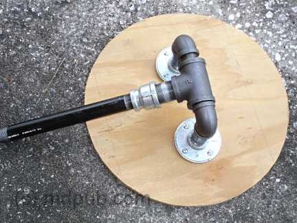 For the tower base, I started by cutting a 2 foot diameter disk out of plywood. I made a U shaped assembly out of 1 inch pipe fittings. In the middle of that assembly I put a 1 1/4 inch Tee. The Tee is free to turn around the 1 inch pipe and forms a hinge that allows me to raise and lower the tower. I then added a close nipple, a 1 1/4 to 1 reducing fitting, and a 12 inch nipple. Later I added a 1 inch Tee between the reducer and the 12 inch nipple so there would be a place for the wires to exit the pipe. This is shown in a photo further down the page. I also later drilled holes in the wooden disk to allow me to use steel stakes to lock it in place on the ground. For the tower base, I started by cutting a 2 foot diameter disk out of plywood. I made a U shaped assembly out of 1 inch pipe fittings. In the middle of that assembly I put a 1 1/4 inch Tee. The Tee is free to turn around the 1 inch pipe and forms a hinge that allows me to raise and lower the tower. I then added a close nipple, a 1 1/4 to 1 reducing fitting, and a 12 inch nipple. Later I added a 1 inch Tee between the reducer and the 12 inch nipple so there would be a place for the wires to exit the pipe. This is shown in a photo further down the page. I also later drilled holes in the wooden disk to allow me to use steel stakes to lock it in place on the ground. 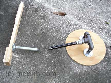 This photo shows the head and base together. You can begin to see how it will go together. Imagine a 10 foot long piece of steel conduit connecting the two pieces. Since I was building this thing in Florida, but was going to use it in Arizona, I decided to hold off on purchasing the 10 foot piece of conduit until I got to Arizona. That meant the wind turbine would never be fully assembled and not get a proper test until I was ready to put it up in the field. That was a little scary because I wouldn't know if the thing actually worked until I tried it in Arizona. This photo shows the head and base together. You can begin to see how it will go together. Imagine a 10 foot long piece of steel conduit connecting the two pieces. Since I was building this thing in Florida, but was going to use it in Arizona, I decided to hold off on purchasing the 10 foot piece of conduit until I got to Arizona. That meant the wind turbine would never be fully assembled and not get a proper test until I was ready to put it up in the field. That was a little scary because I wouldn't know if the thing actually worked until I tried it in Arizona.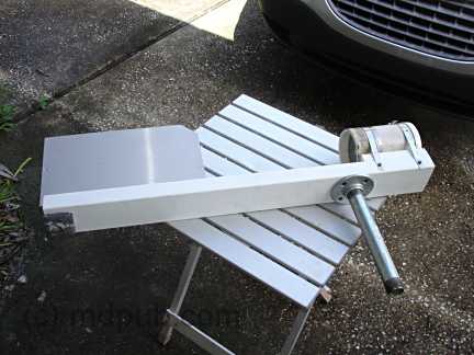 Next, I painted all the wooden parts with a couple of coats of white latex paint I had leftover from another project. I wanted to protect the wood from the weather. This photo also shows the lead counterweight I added to the left side of the 2X4 under the tail to balance the head. Next, I painted all the wooden parts with a couple of coats of white latex paint I had leftover from another project. I wanted to protect the wood from the weather. This photo also shows the lead counterweight I added to the left side of the 2X4 under the tail to balance the head. 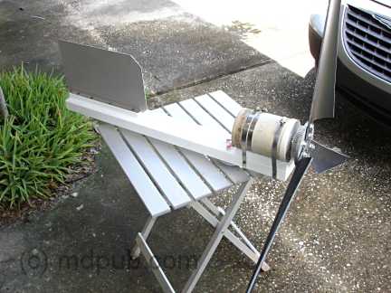 This photo shows the finished head unit with the blades attached. Is that a thing of beauty or what? It almost looks like I know what I'm doing. This photo shows the finished head unit with the blades attached. Is that a thing of beauty or what? It almost looks like I know what I'm doing. I never got a chance to properly test the unit before heading to Arizona. One windy day though, I did take the head outside and hold it high up in the air above my head into the wind just to see if the blades would spin it as well as I had hoped. Spin it they did. In a matter of a few seconds it spun up to a truly scary speed (no load on the generator), and I found myself holding onto a giant, spinning, whirligig of death, with no idea how to put it down without getting myself chopped to bits. Fortunately, I did eventually manage to turn it out of the wind and slow it down to a non-lethal speed. I won't make that mistake again. Now That I had all the mechanical parts sorted out, it was time to turn toward the electronic end of the project. A wind power system consists of the wind turbine, one or more batteries to store power produced by the turbine, a blocking diode to prevent power from the batteries being wasted spinning the motor/generator, a secondary load to dump power from the turbine into when the batteries are fully charged, and a charge controller to run everything. There are lots of controllers for solar and wind power systems. Anyplace that sells alternative energy stuff will have them. There are also always lots of them for sale on Ebay http://www.fieldlines.com/story/2004/9/20/0406/27488 That web site goes into a lot of detail about the controller, so I'm only going to talk about it in fairly general terms here. Again, while I followed their general recipe, I did do some things differently. Being an avid electronics tinkerer from an early age, I have a huge stock of electronic components already on hand, so I had to buy very little to complete the controller. I substituted different components for some parts and reworked the circuit a little just so I could use parts I already had on hand. That way I had to buy almost nothing to build the controller. The only part I had to buy was the relay. Whether you build your own, or buy one, you will need some sort of controller for your wind turbine. The general principal behind the controller is that it monitors the voltage of the battery(s) in your system and either sends power from the turbine into the batteries to recharge them, or dumps the power from the turbine into a secondary load if the batteries are fully charged (to prevent over-charging and destroying the batteries). The schematic and write-up on the above web page does a good job of explaining it. 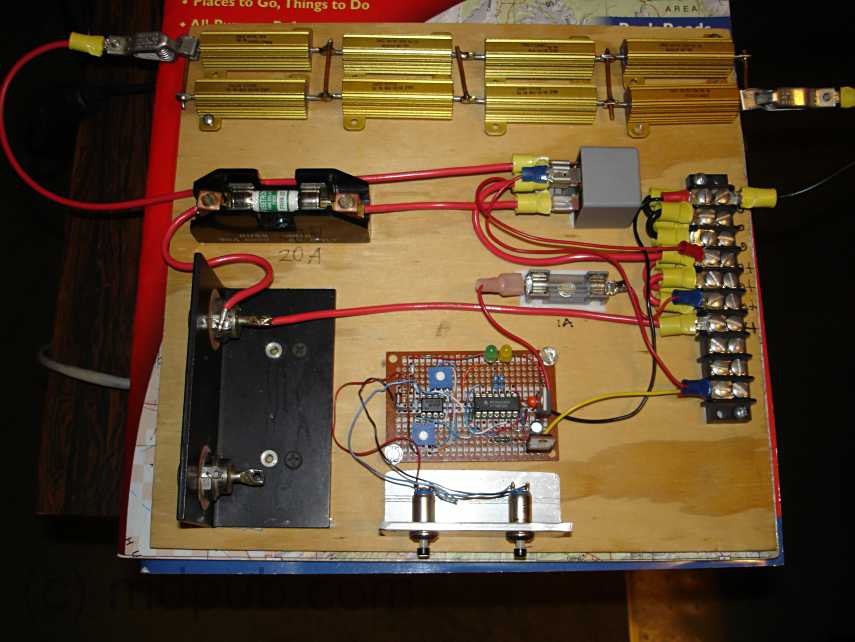 This is a picture of the controller I built. Click on it to see a larger picture. I just bolted everything to a piece of plywood for testing purposes. Eventually I will mount it in a weather-proof enclosure. This is a picture of the controller I built. Click on it to see a larger picture. I just bolted everything to a piece of plywood for testing purposes. Eventually I will mount it in a weather-proof enclosure. The little perf-board in the lower center with the ICs and other bits on it is the actual controller circuit. The silver bracket below it holds two buttons that allow me to manually toggle the unit between charging batteries and dumping power to a secondary load. The big, black heat sink on the lower left has two 40 Amp blocking diodes bolted into it. I am only using one right now, but I could easily add a second wind turbine or even a photovoltaic solar panel to the system using the second one. The double row of gold rectangles across the top is a dummy load made up of high-Wattage resistors. It has taps at 2 Ohm intervals. I use it as a secondary load to dump power from the turbine into when the battery is fully charged. I also use it for testing purposes to load test the turbine. Eventually excess power from the turbine will be dumped to something more useful like a water heater or a second battery bank. Below and to the left of the dummy load is the main fuse for the wind turbine. The small gray cube is a 40 Amp SPDT automotive relay (the only part I had to purchase) which sends the turbine power either to the batteries or to the dummy load. Along the right side is the terminal block which allows me to connect everything together. In operation, the wind turbine is connected to the controller. Lines then run from the controller to the battery. All loads are taken directly from the battery. If the battery voltage drops below 11.9 volts, the controller switches the turbine power to charging the battery. If the battery voltage rises to 14 volts, the controller switches to dumping the turbine power into the dummy load. There are trimpots to adjust the voltage levels at which the controller toggles back and forth between the two states. I chose 11.9V for the discharge point and 14V for the fully charged point based on advice from lots of different web sites on the subject of properly charging lead acid batteries. The sites all recommended slightly different voltages. I sort of averaged them and came up with my numbers. When the battery voltage is between 11.9V and 14V, the system can be switched between either charging or dumping. A pair of push buttons allow me to switch between states anytime, for testing purposes. Normally the system runs automatically. When charging the battery, the yellow LED is lit. When the battery is charged and power is being dumped to the the dummy load, the green LED is lit. This gives me some minimal feedback on what is going on with the system. I also use my multimeter to measure both battery voltage, and turbine output voltage. I will probably eventually add either panel meters, or automotive-style voltage and charge/discharge meters to the system. I'll do that once I have it in some sort of enclosure. I used my variable voltage bench power supply to simulate a battery in various states of charge and discharge to test and tune the controller. I could set the voltage of the power supply to 11.9V and set the trimpot for the low voltage trip point. Then I could crank the voltage up to 14V and set the trimpot for the high voltage trimpot. I had to get it set before I took it into the field because I'd have no way to tune it up out there. Update: I am now using 14.8V for the full charge point after further researching the proper charging of lead-acid batteries. I have also switched to sealed lead-acid batteries because I got a bunch of them free from my brother. I am contemplating switching to deep-cycle batteries when the ones I have now begin to fail. Update: I have found out the hard way that it is important with this controller design to connect the battery first, then connect the wind turbine and/or solar panels. If you connect the wind turbine first, the wild voltage swings coming from the turbine won't be smoothed out by the load of the battery, the controller will behave erratically, the relay will click away wildly, and voltage spikes could destroy the ICs. So always connect to the battery(s) first, then connect the wind turbine. Also, make sure you disconnect the wind turbine first when taking the system apart. Disconnect the battery(s) last. 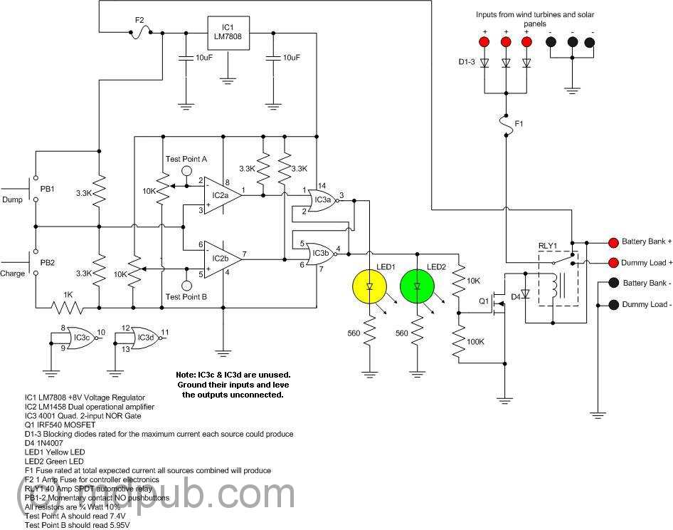 Update: Finally, by very popular demand, I have a schematic of my charge controller. Click on it for the full size schematic. It only varies a little bit from the one at the above link. I substituted a few parts I had on hand for ones in the original design. That way I only had to buy a few things to build the controller. You could do the same. It is not critical to exactly duplicate this design. I used a different op-amp chip and a different MOSFET than the original design. Most of the resistor values are not critical. If you have the knowledge to do so, feel free to substitute. Also, feel free to experiment. I'd be interested in hearing from anyone who feels they have improved on the design in any way. Update: Finally, by very popular demand, I have a schematic of my charge controller. Click on it for the full size schematic. It only varies a little bit from the one at the above link. I substituted a few parts I had on hand for ones in the original design. That way I only had to buy a few things to build the controller. You could do the same. It is not critical to exactly duplicate this design. I used a different op-amp chip and a different MOSFET than the original design. Most of the resistor values are not critical. If you have the knowledge to do so, feel free to substitute. Also, feel free to experiment. I'd be interested in hearing from anyone who feels they have improved on the design in any way.At last, all parts of the project were complete. It was all done only a week before my vacation arrived. That was cutting it close. I disassembled the turbine and carefully packed the parts and the tools I'd need to assemble it for their trip across the country. Then I once again I drove out to my remote property in Arizona for a week of off-grid relaxation, but this time with hopes of having some actual electricity on the site. 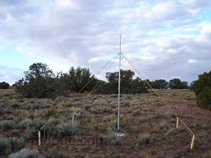 The first order of business was setting up and bracing the tower. After arriving at my property and unloading my van, I drove to the nearest Home Depot (about 60 miles one way) and bought the 10 foot long piece of 1 1/4 inch conduit I needed for the tower. Once I had it, assembly went quickly. I used nylon rope to anchor the pole to four big wooden stakes driven in the ground. Turnbuckles on the lower ends of each guy-line allowed my to plumb up the tower. By releasing the line from either stake in line with the hinge at the base, I could raise and lower the tower easily. Eventually the nylon line and wooden stakes will be replaced with steel stakes and steel cables. For testing though, this arrangement worked fine. The first order of business was setting up and bracing the tower. After arriving at my property and unloading my van, I drove to the nearest Home Depot (about 60 miles one way) and bought the 10 foot long piece of 1 1/4 inch conduit I needed for the tower. Once I had it, assembly went quickly. I used nylon rope to anchor the pole to four big wooden stakes driven in the ground. Turnbuckles on the lower ends of each guy-line allowed my to plumb up the tower. By releasing the line from either stake in line with the hinge at the base, I could raise and lower the tower easily. Eventually the nylon line and wooden stakes will be replaced with steel stakes and steel cables. For testing though, this arrangement worked fine. 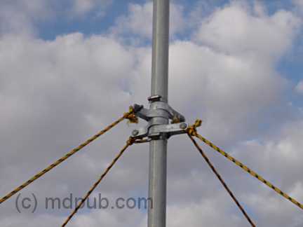 This photo shows a closeup of how the guy-lines attach near the top of the tower. I used chain-link fence brackets as tie points for my guy-lines. The fence brackets don't quite clamp down tightly on the conduit which is smaller in diameter than the fence posts they are normally used with. So there is a steel hose clamp at either end of the stack of brackets to keep them in place. This photo shows a closeup of how the guy-lines attach near the top of the tower. I used chain-link fence brackets as tie points for my guy-lines. The fence brackets don't quite clamp down tightly on the conduit which is smaller in diameter than the fence posts they are normally used with. So there is a steel hose clamp at either end of the stack of brackets to keep them in place.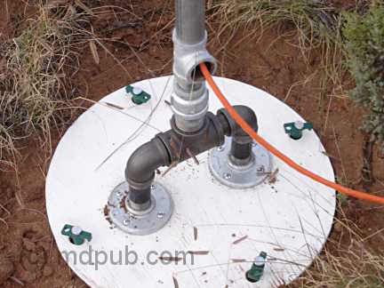 This photo shows the base of the tower, staked to the ground, and with the wire from the wind turbine exiting from the Tee below the conduit tower. I used an old orange extension cord with a broken plug to connect between the turbine and the controller. I simply cut both ends off and put on spade lugs. Threading the wire through the tower turned out to be easy. It was a cold morning and the cord was very stiff. I was able to just push it through the length of the conduit tower. on a warmer day I probably would have had to use a fishtape or string line to pull the cord through the conduit. I got lucky. This photo shows the base of the tower, staked to the ground, and with the wire from the wind turbine exiting from the Tee below the conduit tower. I used an old orange extension cord with a broken plug to connect between the turbine and the controller. I simply cut both ends off and put on spade lugs. Threading the wire through the tower turned out to be easy. It was a cold morning and the cord was very stiff. I was able to just push it through the length of the conduit tower. on a warmer day I probably would have had to use a fishtape or string line to pull the cord through the conduit. I got lucky.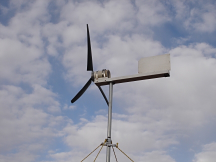 This photo shows the turbine head installed on top of the tower. I greased up the pipe on the bottom of the head and slid it into the top of the conduit. It made a great bearing, just as I'd planned. Sometimes I even amaze myself. This photo shows the turbine head installed on top of the tower. I greased up the pipe on the bottom of the head and slid it into the top of the conduit. It made a great bearing, just as I'd planned. Sometimes I even amaze myself. Too bad there was nobody around to get an Iwo Jima Flag Raising type picture of me raising the tower up with the head installed. Now I'm just waiting for the wind to blow. Wouldn't you know it, it was dead calm that morning. It was the first calm day I had ever seen out there. The wind had always been blowing every other time I had been there. Well, nothing to do but wait. Finally! The wind was up and the turbine was spinning. The winds were actually unusually light the whole time I was on my property this time. The wind turbine still made good amounts of power though, even with winds that at best made it to only a little over 20 mph at times.This photo shows the controller, battery and associated electronics all wired up. I have a 120V inverter connected to the battery and a multimeter to keep track of the battery voltage and wind turbine output voltage. Also my electric shaver and battery charger are plugged into the inverter and running off of 120V AC. Later I plugged a long extension cord into the inverter and stretched it back to my camp site. I know this setup is really messy, but I was in a hurry to get up and running to take advantage of the wind once it started blowing. That's my excuse, and I'm sticking to it. 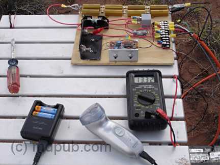 This photo is a closeup of the electronics. The meter shows that the wind turbine is producing 13.32 Volts. My electric shaver and battery charger are providing loads on the system through the AC inverter. This photo is a closeup of the electronics. The meter shows that the wind turbine is producing 13.32 Volts. My electric shaver and battery charger are providing loads on the system through the AC inverter.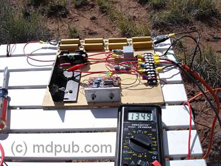 Here the meter shows the turbine producing 13.49 volts. The voltage from the turbine goes up only a little as the wind speed increases once it has a load to power. Once the wind starts blowing, the turbine head snaps around into it and begins spinning up. It spins up quickly until the output voltage exceeds the battery voltage plus the blocking diode drop (around 13.2 volts, depending on the state of the battery charge). it is really running without a load until that point. Once the that voltage is exceeded, the turbine suddenly has a load as it begins dumping power into the battery. Once under load, the rpms only slightly increase as the wind speed increases. More wind means more current into the battery which means more load on the generator. So the system is pretty much self-governing. I saw no signs of over-reving. Of course in storm-force winds, all bets are off. Switching the controller to dump power into the dummy load did a good job of braking the turbine and slowing it way down even in stronger gusts. Actually shorting the turbine output is an even better brake. It brings the turbine to a halt right now, even in strong winds. Shorting the output is how I made the turbine safe to raise and lower, so I wouldn't get sliced and diced by the spinning blades. Warning though, the whole head assembly can still swing around and crack you hard on the noggin if the wind changes direction while you are working on these things. So be careful out there. Here the meter shows the turbine producing 13.49 volts. The voltage from the turbine goes up only a little as the wind speed increases once it has a load to power. Once the wind starts blowing, the turbine head snaps around into it and begins spinning up. It spins up quickly until the output voltage exceeds the battery voltage plus the blocking diode drop (around 13.2 volts, depending on the state of the battery charge). it is really running without a load until that point. Once the that voltage is exceeded, the turbine suddenly has a load as it begins dumping power into the battery. Once under load, the rpms only slightly increase as the wind speed increases. More wind means more current into the battery which means more load on the generator. So the system is pretty much self-governing. I saw no signs of over-reving. Of course in storm-force winds, all bets are off. Switching the controller to dump power into the dummy load did a good job of braking the turbine and slowing it way down even in stronger gusts. Actually shorting the turbine output is an even better brake. It brings the turbine to a halt right now, even in strong winds. Shorting the output is how I made the turbine safe to raise and lower, so I wouldn't get sliced and diced by the spinning blades. Warning though, the whole head assembly can still swing around and crack you hard on the noggin if the wind changes direction while you are working on these things. So be careful out there. 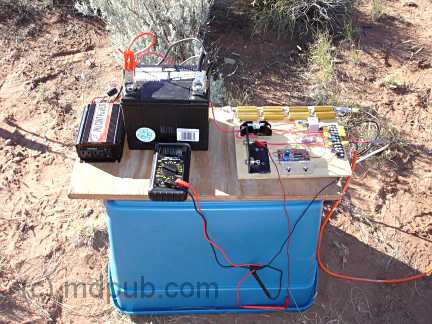 Eventually I decided my setup was too messy and dangerous. Having high current electrical connections and a rat's nest of wires on an Aluminum table wasn't smart. The danger of a spectacular short circuit was too high, so I neatened things up. I set all the electronics on a piece of plywood on top of a plastic storage bin and neatened up the wiring. Then I ran a long extension cord from the inverter back to my camp site and plugged all my stuff into it there. Eventually I decided my setup was too messy and dangerous. Having high current electrical connections and a rat's nest of wires on an Aluminum table wasn't smart. The danger of a spectacular short circuit was too high, so I neatened things up. I set all the electronics on a piece of plywood on top of a plastic storage bin and neatened up the wiring. Then I ran a long extension cord from the inverter back to my camp site and plugged all my stuff into it there. 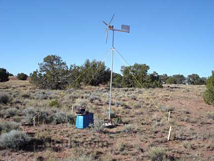 Here is a longer view of the complete setup. Here is a longer view of the complete setup. 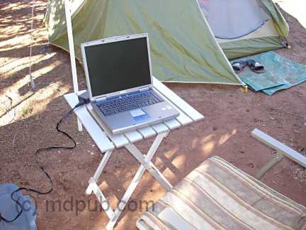 How sweet it is! I have electricity! Here I have my laptop computer set up and plugged into the power provided by the inverter, which in turn is powered by the wind turbine. I normally only have about two hours of battery life on my laptop. So I don't get to use it much while I'm camping. It comes in handy though for downloading photos out of my camera when its memory card gets full, making notes on projects like this one, working on the next great American novel, or just watching DVD movies. Now I have no battery life problems, at least as long as the wind blows. Besides the laptop, I can also now recharge all my other battery powered equipment like my cell phone, my camera, my electric shaver, my air mattress pump, etc. Life used to get real primitive on previous camping trips when the batteries in all my electronic stuff ran down. How sweet it is! I have electricity! Here I have my laptop computer set up and plugged into the power provided by the inverter, which in turn is powered by the wind turbine. I normally only have about two hours of battery life on my laptop. So I don't get to use it much while I'm camping. It comes in handy though for downloading photos out of my camera when its memory card gets full, making notes on projects like this one, working on the next great American novel, or just watching DVD movies. Now I have no battery life problems, at least as long as the wind blows. Besides the laptop, I can also now recharge all my other battery powered equipment like my cell phone, my camera, my electric shaver, my air mattress pump, etc. Life used to get real primitive on previous camping trips when the batteries in all my electronic stuff ran down. So how much did all this cost to build? Well, I saved all the receipts for everything I bought related to this project.
Future modifications and enhancements I would like to make to the system include:
As the project evolves in the future, I'll post updates here. UPDATE 03/19/07 This web site has become very popular. Thank you all for your interest and encouragement. I am getting tons of email questions from people about all sorts wind power related (and not so related) issues. Many are the same few questions asked over and over again. Unfortunately I simply don't have the time to answer them all. I do try to read them all, but my busy schedule simply doesn't allow enough time to respond to most of them. So don't take it personally if you don't get a response. I'll instead post responses to the most commonly asked questions here as time allows. Question #1: How do you prevent the power cable coming down the inside of the tower from winding up over time? Answer: This is by far the most asked question I get from people. The short answer is I don't do anything to prevent it. The cable really doesn't wind up all that badly. The wind is as liable to spin the turbine head around one way as it is the other. So there is no real tendency for the cable to wind up badly. If it does wind up over time, it is no big deal to simply disconnect the wires at the bottom and manually unwind it. I have an idea for a fairly easy to build slip-ring system that would prevent any possibility of winding up the cable. At present though, there is little need to actually try implementing it. Maybe I'll try it out on a future turbine. Update: Here is a video explaining the wire twisting issue. Question #2: Can you help me design/build a wind power system that will power my whole home/farm so I can get out from under the thumb of my evil electric utility company? Answer: The short answer is no. Not just due to time constraints, but also because my system isn't designed to produce enough electricity to power an entire home or farm. My system was just designed to provide a couple of hundred Watts tops in an area where no other electric options were available. I am working on design and construction of other wind turbines and even solar panels to increase my power production beyond the current minimal level. However, even if successful, these new additions would still not power a typical home or farm. My ultimate goal is to have enough power from wind and solar sources to power a small cabin and observatory on my remote property that will only be occupied occasionally and won't have much need for electricity. If you need a bigger system, then you need someone with experience with bigger systems to help you out. Question #3: What are you working on now? Answer: As time permits I am reworking the charge controller. It is going to be mounted in a weather-proof case with automotive-style voltage and amp meters installed on it. I have all the parts I need, but time to work on it is lacking. I am also working on a new design for the turbine head that will automatically turn out of the wind if it gets too strong so as to prevent over-speed damage. I have also started work on building a solar panel out of cheaply acquired solar cell seconds (from Ebay UPDATE 05/17/07 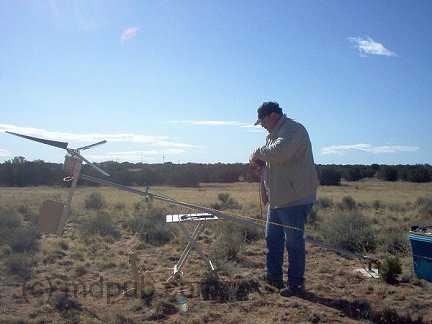 Here is a photo of me setting up the wind turbine on my remote property during our May 2007 trip to Arizona. I had left most of the equipment on-site in Arizona. I only brought the turbine head and charge controller back home with me. Everything weathered the winter ok. Just some slight surface rust on parts of the tower base. Everything went back together quickly and worked great. Here is a photo of me setting up the wind turbine on my remote property during our May 2007 trip to Arizona. I had left most of the equipment on-site in Arizona. I only brought the turbine head and charge controller back home with me. Everything weathered the winter ok. Just some slight surface rust on parts of the tower base. Everything went back together quickly and worked great. 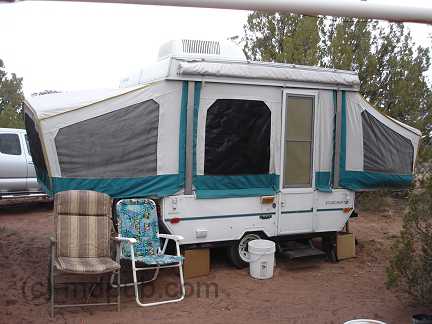 I used the wind turbine to power my new popup trailer on my spring vacation. The strong spring winds kept the wind turbine spinning all day every day and most of the nights too while I was in Arizona. The turbine provided enough power for the interior 12V lighting and enough 120V AC at the power outlets to keep my battery charger, electric shaver, and mini vacuum cleaner (camping is messy) all charged up and running. My girlfriend complained about it not having enough power to run her blow-dryer though. I used the wind turbine to power my new popup trailer on my spring vacation. The strong spring winds kept the wind turbine spinning all day every day and most of the nights too while I was in Arizona. The turbine provided enough power for the interior 12V lighting and enough 120V AC at the power outlets to keep my battery charger, electric shaver, and mini vacuum cleaner (camping is messy) all charged up and running. My girlfriend complained about it not having enough power to run her blow-dryer though. 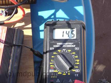 Here my volt meter is showing the turbine producing 14.5 volts in a stiff wind. Although the wind turbine powered the popup fairly well, I think there is room for improvement. I was powering the popup with 120 Volts AC via my inverter. The popup has its own 120V AC to 12V DC power supply for powering the interior lighting and other 12V accessories. The losses involved in converting power to 120V AC and then back to 12V DC probably heavily contributed to the battery running down fairly quickly a couple of times during periods of light wind. Powering the 12V systems directly from the battery would probably work better. The only downside I see is that the DC voltage won't be regulated and could swing a couple of volts up or down with changes in wind speed. That wouldn't bother most kinds of lighting too much. Other devices could have a problem with it though. Here my volt meter is showing the turbine producing 14.5 volts in a stiff wind. Although the wind turbine powered the popup fairly well, I think there is room for improvement. I was powering the popup with 120 Volts AC via my inverter. The popup has its own 120V AC to 12V DC power supply for powering the interior lighting and other 12V accessories. The losses involved in converting power to 120V AC and then back to 12V DC probably heavily contributed to the battery running down fairly quickly a couple of times during periods of light wind. Powering the 12V systems directly from the battery would probably work better. The only downside I see is that the DC voltage won't be regulated and could swing a couple of volts up or down with changes in wind speed. That wouldn't bother most kinds of lighting too much. Other devices could have a problem with it though. 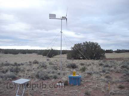 This photo shows the turbine spinning away and cranking out the power. I haven't had the time to complete the rebuild of the charge controller in a weather-proof enclosure. So this time I just put all the electronics in a plastic bin to protect them from the elements. Good thing too, since it rained several times while we were there this time. The jug of lamp oil is on top of the bin to prevent the wind from ripping the lid off. This photo shows the turbine spinning away and cranking out the power. I haven't had the time to complete the rebuild of the charge controller in a weather-proof enclosure. So this time I just put all the electronics in a plastic bin to protect them from the elements. Good thing too, since it rained several times while we were there this time. The jug of lamp oil is on top of the bin to prevent the wind from ripping the lid off. UPDATE 01/3/08 I have completed my first home-built solar panel. It will be used in addition to the wind turbine to produce more power on my remote Arizona land. UPDATE 05/20/08 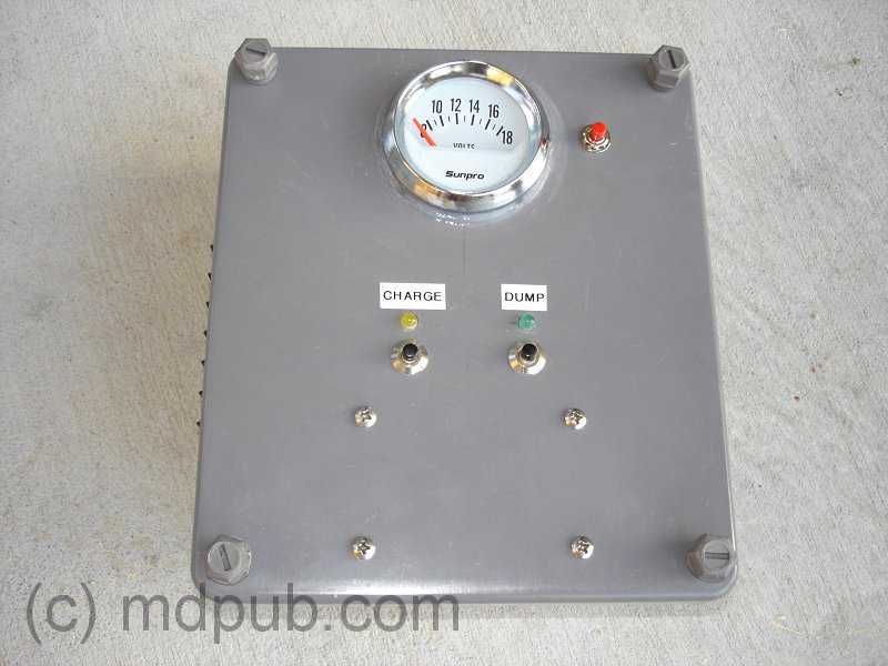 I have completed the rebuild of the charge controller. It is now in a semi-weatherproof enclosure and I have added a built in voltage meter. I have also added a few new features. The unit now has provisions for power inputs from multiple sources. It also has built-in fused 12V power distribution for three external loads. I have completed the rebuild of the charge controller. It is now in a semi-weatherproof enclosure and I have added a built in voltage meter. I have also added a few new features. The unit now has provisions for power inputs from multiple sources. It also has built-in fused 12V power distribution for three external loads.  This photo shows the inputs to the charge controller. It has provisions for 3 inputs. One for my wind turbine and two for solar panels, though I only have one solar panel complete at this time. This photo shows the inputs to the charge controller. It has provisions for 3 inputs. One for my wind turbine and two for solar panels, though I only have one solar panel complete at this time. 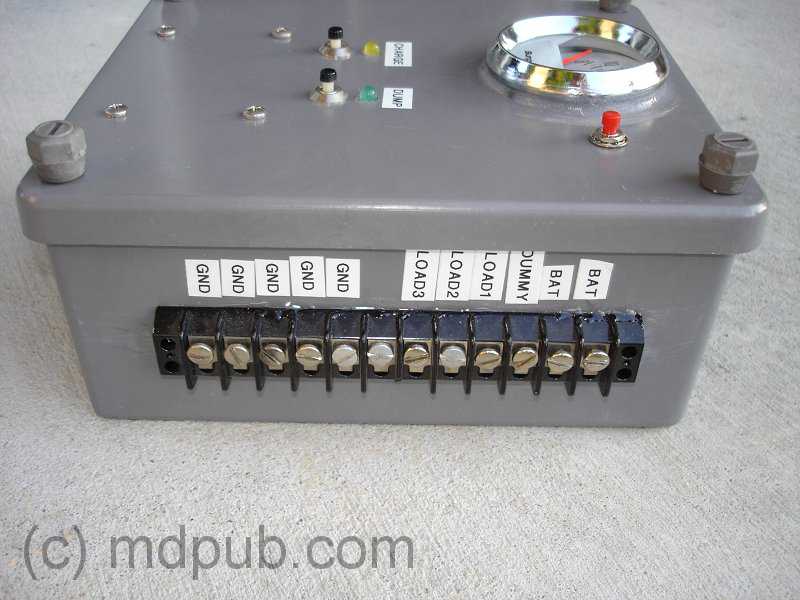 This photo shows the outputs from the charge controller. There are connections to the battery bank(s), dummy load, and three fused external 12V loads. This photo shows the outputs from the charge controller. There are connections to the battery bank(s), dummy load, and three fused external 12V loads. 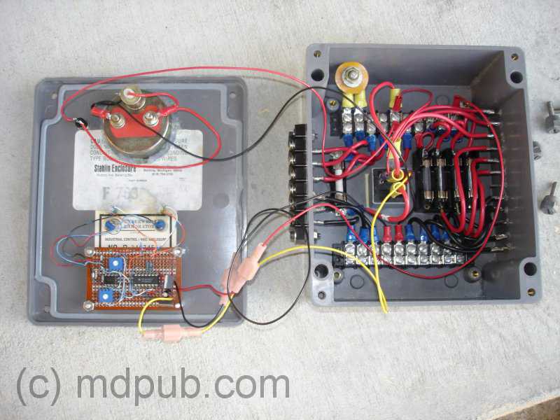 This photo shows the inside of the charge controller. I basically just transferred everything that I originally had bolted onto the plywood board in the prototype into this box. I added an automotive illuminated voltage gage and fuses for 3 external 12V loads. I used heavy gage wire to try to reduce losses due to wire resistance. Every watt counts when you are living off-grid. This photo shows the inside of the charge controller. I basically just transferred everything that I originally had bolted onto the plywood board in the prototype into this box. I added an automotive illuminated voltage gage and fuses for 3 external 12V loads. I used heavy gage wire to try to reduce losses due to wire resistance. Every watt counts when you are living off-grid. 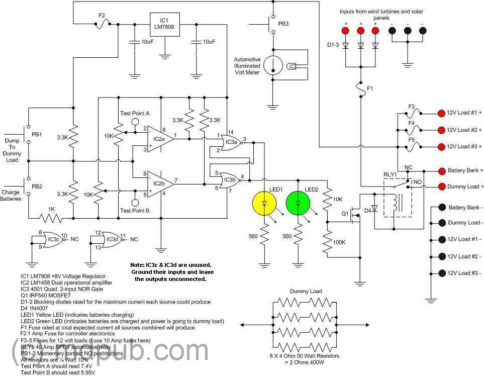 This is the schematic for the new charge controller. It is pretty much the same as the old one above, except for the addition of the Volt meter and extra fuse blocks for the external loads. Click on it for a larger version. This is the schematic for the new charge controller. It is pretty much the same as the old one above, except for the addition of the Volt meter and extra fuse blocks for the external loads. Click on it for a larger version. 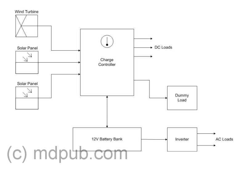 This is a block diagram of the whole power system. click on it for a larger version. Note that I only have one solar panel built right now. I just haven't had the time to complete the second one. Please visit my home-built solar panel page. This is a block diagram of the whole power system. click on it for a larger version. Note that I only have one solar panel built right now. I just haven't had the time to complete the second one. Please visit my home-built solar panel page. UPDATE 07/18/08  Once again I stayed on my remote property during my recent vacation in Arizona. This time I had both my home-built wind turbine and my home-built solar panel with me. Working together, they provided plenty of power for my (admittedly minimal) electricity needs. Once again I stayed on my remote property during my recent vacation in Arizona. This time I had both my home-built wind turbine and my home-built solar panel with me. Working together, they provided plenty of power for my (admittedly minimal) electricity needs. 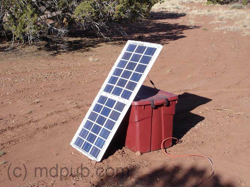 Here is a close-up of the solar panel. A write-up on how I built it can be found here. I have to move it several times each day to keep it pointed at the sun, but that isn't really a big hardship. Maybe someday I will build a tracking system to automatically keep it aimed at the sun. Here is a close-up of the solar panel. A write-up on how I built it can be found here. I have to move it several times each day to keep it pointed at the sun, but that isn't really a big hardship. Maybe someday I will build a tracking system to automatically keep it aimed at the sun. 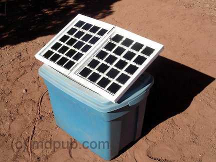 I have finally completed my second home-built solar panel. This is a smaller 15 Watt panel. It folds up for easier storage and transportation. Click the photo to learn more about it. I have finally completed my second home-built solar panel. This is a smaller 15 Watt panel. It folds up for easier storage and transportation. Click the photo to learn more about it. 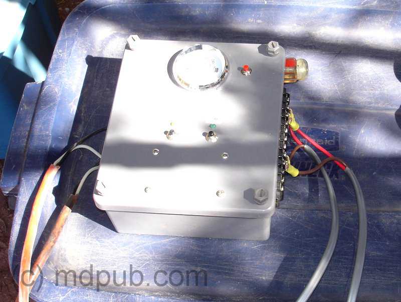 Here is a photo of the new charge controller unit. The wires on the left side are coming from the wind turbine and solar panel. The wires on the right side are going to the battery bank and dummy load. I cut up an old heavy-duty 100 ft. extension cord to make cables to connect wind turbine and solar panel to the charge controller. The cable to the wind turbine is about 75 feet long and the cable to the solar panel is about 25 feet long. The battery bank I am currently using consists of 11 sealed lead-acid 12V batteries of 8 Amp-Hour capacity connected in parallel. That gives me 88 Amp-Hours of storage capacity, which is plenty for camping. As long as it is sunny and windy, (nearly every day is sunny and windy on my property), the wind turbine and solar panel keep the batteries well charged. Here is a photo of the new charge controller unit. The wires on the left side are coming from the wind turbine and solar panel. The wires on the right side are going to the battery bank and dummy load. I cut up an old heavy-duty 100 ft. extension cord to make cables to connect wind turbine and solar panel to the charge controller. The cable to the wind turbine is about 75 feet long and the cable to the solar panel is about 25 feet long. The battery bank I am currently using consists of 11 sealed lead-acid 12V batteries of 8 Amp-Hour capacity connected in parallel. That gives me 88 Amp-Hours of storage capacity, which is plenty for camping. As long as it is sunny and windy, (nearly every day is sunny and windy on my property), the wind turbine and solar panel keep the batteries well charged. 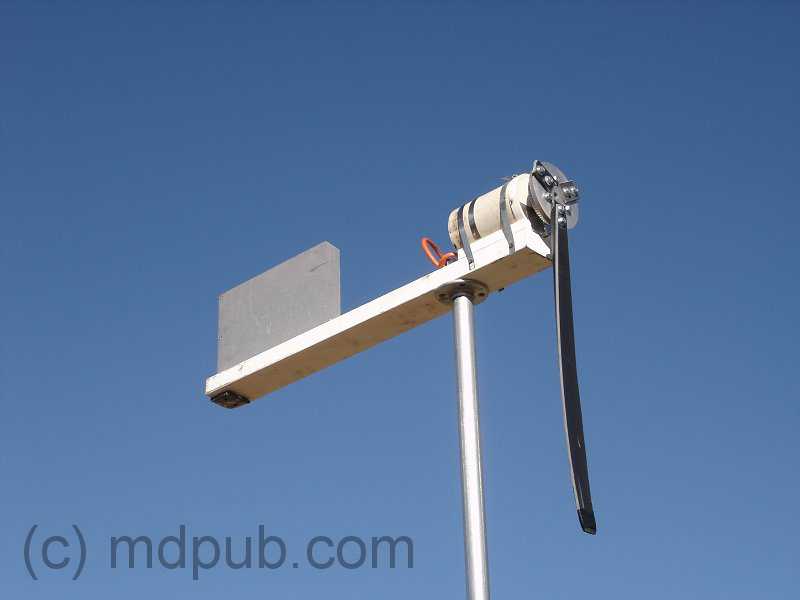 Disaster! I went into town to pick up some supplies. While I was gone, a wind storm came up. Winds well in excess of 50 MPH blew through my area. When I returned I found the turbine in this condition. Two blades had snapped off, and the third was cracked, but still attached. The blades broke where the mounting tab met the body of the blade. I knew this was a weak spot and always expected they would break there eventually. I don't know for sure if it was over-speed, or just fatigue from repeated flexing that caused them to break. I suspect fatigue though. I could see the blades flexing in strong winds before they broke. Interestingly though, I found that the battery bank was fully charged. The wind turbine must have generated some serious power in those high winds before it failed. Disaster! I went into town to pick up some supplies. While I was gone, a wind storm came up. Winds well in excess of 50 MPH blew through my area. When I returned I found the turbine in this condition. Two blades had snapped off, and the third was cracked, but still attached. The blades broke where the mounting tab met the body of the blade. I knew this was a weak spot and always expected they would break there eventually. I don't know for sure if it was over-speed, or just fatigue from repeated flexing that caused them to break. I suspect fatigue though. I could see the blades flexing in strong winds before they broke. Interestingly though, I found that the battery bank was fully charged. The wind turbine must have generated some serious power in those high winds before it failed. I knew I could get the wind turbine up and running again if I could just drill new mounting holes in the blades. I had no drill or drill bits with me though. I had to think about it for a while before I figured out how to do it. Then, the spirit of MacGyver came over me, and I knew just how to do it.  I figured out that if I heated my largest Phillips screwdriver over a fire, it would melt a hole in the PVC blades just the right size for the mounting bolts. So I got some charcoal going and started making holes. It's a terrible abuse of a perfectly good screwdriver, but it was an emergency situation after all. I figured out that if I heated my largest Phillips screwdriver over a fire, it would melt a hole in the PVC blades just the right size for the mounting bolts. So I got some charcoal going and started making holes. It's a terrible abuse of a perfectly good screwdriver, but it was an emergency situation after all. 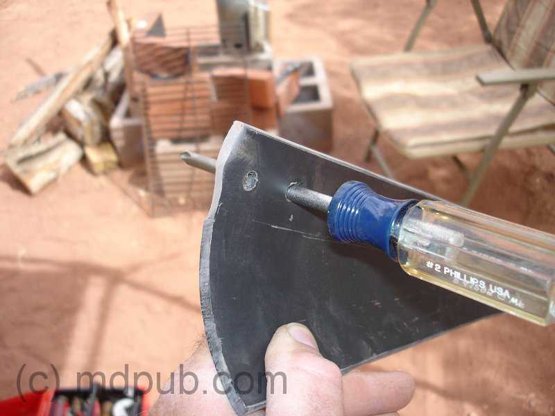 I used one of the broken mounting tabs as a template to locate where to make the holes in the bases of the blades. Then it was straightforward to just melt through the blades with the screwdriver. It was very quick and easy, and the holes were very clean. I used one of the broken mounting tabs as a template to locate where to make the holes in the bases of the blades. Then it was straightforward to just melt through the blades with the screwdriver. It was very quick and easy, and the holes were very clean. 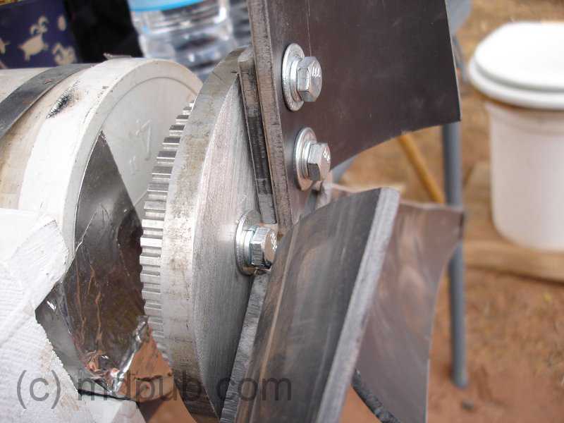 I then re-mounted the blades on the hub of the turbine. I used the broken mounting tabs as spacers under the blades to prevent them from fouling the heads of the bolts that hold the hub together. The tabless blades are much stronger and less likely to flex in strong winds. I should have done it this way in the beginning. Live and learn. I then re-mounted the blades on the hub of the turbine. I used the broken mounting tabs as spacers under the blades to prevent them from fouling the heads of the bolts that hold the hub together. The tabless blades are much stronger and less likely to flex in strong winds. I should have done it this way in the beginning. Live and learn. 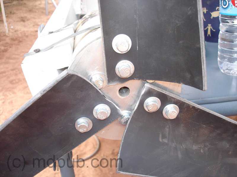 Here is the turbine all re-assembled and ready to go back up on the tower. Here is the turbine all re-assembled and ready to go back up on the tower.  Here is the wind turbine up and flying again. The loss of two inches of blade length doesn't seem to have adversely impacted the performance of the turbine. It still works great. Not bad for an improvised repair job. Here is the wind turbine up and flying again. The loss of two inches of blade length doesn't seem to have adversely impacted the performance of the turbine. It still works great. Not bad for an improvised repair job. |